Welcome, Autel Pilots!
Join our free Autel drone community today!
Join Us

RTK EVO TEST 2 with attached data

If I'm reading the report correctly, is says that the GCP mean RMS error is .69 inches (.018 m) and the camera position mean RMS error is .42 feet. I think the GCP should be set to at max .005 meters which is what you have in P4D, correct?
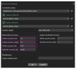
In DD you can not change these settings. DD does not use Pix engines has not for a long time

DD is starting to SUCK, for RTK drones!!
 
Last edited:
Using Metashape

Marker #6 as GCP
Markers #1- #5 as Checkpoints.

Note metrics are in feet, not meters.
Checkpoints mean error X/Y .83 feet = 1 inch ..... Z .1 feet = 1.2 inch

I would be very happy with that. Jeff, if you have easy access to that site, I would suggest running it again a couple of times with increasing altitude to find out how much higher you can go and retain the accuracy. For example, if you can fly it at double or even triple the altitude and retain the accuracy would be a big factor if/when you are tasked with scanning 100 acres or more. At 80' you'll need to bring your tent and a generator, lol.

MS.JPG
 
Last edited:
  • Like
Reactions: jmason702
Thank you Sir! I will run it again next weekend. I am playing with meta shape now. this test was 80ft AGL, 5MPH 80 Front, and 70 side

Next time Ill fly at 200 ft AGL and same overlap and at 9MPH
 
  • Like
Reactions: Dave Pitman
1. 300ft AGL; max 18mph; 75% front overlap; 65% side overlap; 90deg camera single grid for *flat areas [absolute accuracy ~2inches]
2. 250ft AGL; max 15mph; 75% front overlap; 70% side overlap; 90deg single grid for *flat areas [absolute accuracy ~1inch]
3. 200ft AGL; max 12mph; 75% front overlap; 75% side overlap; 60deg double grid for urban areas [absolute accuracy ~1inch] + add 2 orbits on 300ft and 250ft for higher vertical objects.
4. 150ft AGL; max 8mph; 80% front overlap; 80% side overlap; oblique mode for small areas [absolute accuracy ~1inch]

*flat - few tall horizontal objects in the area. Elements such as embankments, excavations or ditches are still mapped.
For all shutter priority 1/200-1/1000 depending on lightning conditions.

Most of the times i'm using 1. for monthly earthwork calculations on road construcion sites, 2. for more precise calculations on storage yards or at the request of the client.
3 combined with 4 works great for highly detailed 3d textured models .
WOW! That's great info here!
 
What settings are you guys using when just using an RTK drone, no checks or GCPs? Please and thank you
 

Attachments

  • AGI.jpg
    AGI.jpg
    87.1 KB · Views: 11
What settings are you guys using when just using an RTK drone, no checks or GCPs? Please and thank you

You could do a quick test with your RS2. Let it occupy a point for 5 min after fix, record the coordinates and then occupy the same point with the drone for 5 min after fix and compare the coordinates. You'll have to do a little fuzzy math to account for the sensor height but you should expose some sort of variance. Note, I'm just winging it here, but it should work. Place the drone on the point so that where you guess the sensor would be is directly over the point.
 
  • Like
Reactions: jmason702
You could do a quick test with your RS2. Let it occupy a point for 5 min after fix, record the coordinates and then occupy the same point with the drone for 5 min after fix and compare the coordinates. You'll have to do a little fuzzy math to account for the sensor height but you should expose some sort of variance. Note, I'm just winging it here, but it should work. Place the drone on the point so that where you guess the sensor would be is directly over the point.
My PPK does this for a "calibration target" or GCP.

I place the drone directly over the center of the target and use the grid system option to align it perfectly. I then subtract the distance from the center of the target to the phase center of the antenna.

I compared this to RS2 collected in RTK and it was within millimeters.

The PPK company BAAMTech states that this calibration target helps it so you don't need to have a perfect camera calibration. In my few tests so far it has proven to be very accurate.

Without this calibration target the map always had a vertical shift.
 

Latest threads

Members online

No members online now.

Forum statistics

Threads
11,281
Messages
102,957
Members
9,880
Latest member
chuckster58