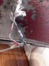
Hi Quad, I never modified a USB-A to USB-C cable, just constructed the adapters described in my post. IMO there isn't any reason why modifying an existing USB-A to USB-C cable shouldn't work. The four wires in a USB-A to USB-C cable are:
USB Ground : Black
USB Data + : Blue
USB Data - : White
USB Vcc : Red
One needs to cut the USB Ground (black wire) and solder the resister to each end of the cut USB Ground wire. The resistor must be 39 ohms or less, 20 ohms preferred.
If that doesn't work, I suspect that the resistor value isn't what you think it is. Double check with an ohmmeter. Hope this helps.
BTW, do you have a YouTube channel, 808-State? IMO that YouTube channel always contains valuable information on the
EVO II Pro and accessories like the Sky Fire Aerial tablet mounts. I learn a lot from and always look forward to new 808-State videos.
Regards,
Richard